I recently finished implementing a hole-closing mechanism on top of three.js geometry and math types. The algorithm is based on the first few sections of “A robust hole-filling algorithm for triangular mesh” (Zhao, W., Gao, S. & Lin, H. Visual Comput (2007) 23: 987. doi:10.1007/s00371-007-0167-y), filling the unstated implementation details within the constraints of computing everything in a browser. I will explain more in words than in code because there’s a lot of code. I’ll write the code in a nonspecific combination of pseudocode and JS.
The algorithm is superficially simple: find cycles of boundary vertices (vertices that border holes), then, for each cycle, fill in the hole by advancing the front of vertices into the hole according to the above paper’s Fig. 3.
Terminology (obvious if familiar with three.js, feel free to skip)
A “vertex” (plural: “vertices”, not “vertexes”) will be represented by a THREE.Vector3 object. Each of these contains three floating-point numbers and a pile of useful functions in its prototype (dot, cross, normalize, and so on).
“Face” will denote a triangle represented by a THREE.Face3 object. This object’s contents relevant to the current discussion are three indices into a vertex array and a vector signifying the normal. The normal is assumed to be normalized. Faces always follow a CCW winding order: looking along the negative normal, index b is CCW from a and c is CCW from b.
“Edge” will denote a (usually ordered) pair of vertices or, equivalently, the vector between them: if the vertices are v1 and v2, the edge “from v1 to v2” is v2-v1.
Setup
Our starting data structures look like this: an array of THREE.Vector3s representing the mesh’s vertices and an array of THREE.Face3s, each representing a face with its vertices among the vertex array. The vertices are assumed to be unique. We have no explicit representation of edges.
1. Make an adjacency map
First, we’ll build a hash table containing adjacency information for the vertices. The key is a hash generated from a vector: a vector like [1.28573568, 0.00584586, 10.86187359] will produce a hash like "128574_585_1086187". The value at the hash for a particular vertex is an object like this:
adjacencyMap[hash] = {
  neighbors = [...],
  normal = vector,
  windingOrder = [...]
}
neighbors is an array of vertices adjacent to the given vertex. “Adjacency” of two vertices means that there is at least one face that contains both vertices.
normal is the normal vector at the vertex (see below for details).
windingOrder corresponding to neighbor v1 in the hash table entry for vertex v is computed thusly: it is 1 if v1 is CCW from v when looking along the negative face normal; else it’s -1. This simply tell us whether the geometry is on the left or the right. I originally had a complicated calculation for this along the lines of sign( ((v2-v1) cross n) dot (v3-v1) ), which computed the same thing, until I realized that you can just figure it out from the order of face indices.
(If one were in the mood to optimize, one would note that every entry in the windingOrder is really a single bit, in our scheme holding the value of 1 or -1; one could replace the whole thing with a bitmap, making storage more efficient).
In practice, one would implement this structure by iterating over the array of faces and adding an entry to the adjacency map for every pair of vertices in the face (given one vertex, add both of its neighbors to its hash table entry and calculate the two corresponding windingOrder values).
There’s a problematic bit here with calculating the vertex normal. How do? Ideally, I want the vertex normal to always have a positive component along the face normals of every adjacent face. There are three dominant options, according to a perusal of StackOverflow:
- add the normals of the adjacent faces
- add the normals of the adjacent faces, weighted by face area
- add the normals of the adjacent faces, weighted by each face’s angle at the vertex
Now, 1 is the simple version; however, it’s easy to think of a scenario where the resulting vector might become heavily biased in one direction because there are lots of faces there.
2 makes no sense.
3 is the option I’m using. I think it can still result in a bad vector (negative component along one or more adjacent face normals), but much more rarely.
2. Extracting the border vertices
Note that the windingOrder entry for the edge from v1 to v2 on face f will have the opposite sign than the corresponding entry for the same edge from an adjacent face. This means that, if we add the windingOrder values for every edge, we will only have nonzero windingOrder entries on edges that border an odd number of faces; assuming there are no edges bordering more than two vertices, we can use this fact to find the boundary vertices.
We now either modify the original hash table or build a second one - we will refer to the structure containing the border vertices as the “border vertex map”. This thing will have an entry for every vertex that has at least one nonzero windingOrder entry in its adjacency map entry. Note that, for every hole bordering a vertex, the vertex will have two outgoing edges with nonzero windingOrder entries; so the number of holes adjacent to a vertex will be the half its number of nonzero windingOrder entries.
3. Extracting cycles of boundary vertices
This is the hard part.
Now, the basic algorithm is simple: pick a random vertex from our set of boundary vertices, find a neighbor on the boundary, and keep walking forward along its neighbors until we hit the starting vertex.
But what happens if we have vertices that border multiple holes? We might take the wrong turn at such a vertex, and this could lead to a rich plethora of problems which, while deterministic, are pretty much random from a user’s perspective. Back when I didn’t have the windingOrder array above, I came up with a few exotic solutions. Among those was a function that did minimal patching of every vertex bordering multiple holes such that the holes would become isolated from each other; after this, you’d be able to do the simple scheme above. But everything I tried started feeling like a tower of duct tape, and duct tape begets errors.
Additionally, there’s the issue of winding order. To fill the hole with faces, we need to wind them correctly (CCW in three.js’s case), so it would very much help if we wound the cycle of boundary edges in a consistent way. Let’s say that henceforth we’re winding CW.
The windingOrder array provides easy-ish fixes to both quandaries and lets us implement the following scheme:
To start constructing a cycle, find a vertex that borders only one hole - this should always exist if there are more vertex cycles to be found. Pick one of its neighbors and check the windingOrder of that edge. The sign of the winding order tells us whether the adjacent face is on the left or right when looking along the negative normal. If the face is on the left, that means we’re winding CW and everything is correct; if it’s on the right, we choose the other neighbor of the current vertex instead. Then we just proceed along the cycle as in the basic algorithm.
When we encounter a vertex bordering multiple holes, we need to do some magic. The scheme here is like this: take all the outflowing edges from the current vertex and project out their component along the normal. So we now have an axis (the normal) with a fan of edges (orthogonal to the axis) flowing out of the vertex. Now just calculate the angles of the edges with respect to the edge going to the previous vertex; pick the first edge that’s CCW from the previous edge. That edge will correspond to the correct next vertex.
4. Filling a hole
A bit fiddly, but not too difficult.
First, take the array of vertices corresponding to a border cycle. Call it cycle. It’s prudent to also store an array of normals (normals) corresponding to each vert and an array of angles (angles). The angles array contains the angles formed by the two outflowing edges from a given vertex. One must take care here: the obvious way of calculating the angles is something like acos(e1 dot e2), but the inverse cosine only returns values between 0 and pi. To detect angles greater than pi, one would calculate one edge crossed with the normal, then dotted with the other edge; the sign of this term indicates whether the vertex is protruding into the hole. If it’s indeed protruding, subtract the angle from 2pi.
Now, until the hole is filled, repeat the following at each iteration. Pick the vertex with the lowest angle. If the angle is , just make a face with the vertex and its two neighbors. If , add an extra vertex and form two faces. If angle is , make two new vertices and three faces. If at any step the newly formed edges have length below a given threshold, merge them.
Two key points above are unspecified in the paper, so I came up with makeshift heuristics to make my algorithm work.
- Where exactly do we create new vertices? I linearly interpolated the length and the angle between the two neighbors of the original vertex, so the new fan of faces created off the current vertex is uniformly spaced with respect to the vertex’s neighbors. I also added a vector pointing at the center of the hole, scaled to a set fraction (
0.2) of(v'-v)(wherevis the smallest-angle vert andv'is a newly formed vert adjacent to it) and decreasing in magnitude with increasing proximity to the center. I found that this works, though I consider it a very crude heuristic. - How do we pick the threshold below which to merge vertices? I found that the average length of the edges in the original border cycle worked fairly well.
After forming one or more faces at each step, we must update cycle (we either destroyed a vertex, replaced a vertex with another, or added one), angles (calculate new angles for the verts that underwent changes), and normals. There’s a fiddly aspect to recalculating normals: so we have a vertex with a normal, and we add a face that’s adjacent to it - how do we adjust its normal? I decided that I’d add the old normal plus the new one, each weighted by its angle contribution at the vertex. Unfortunately, this wasn’t enough; I had to double the angle contribution from the new face, so the normal is biased slightly toward the new face. I regrettably don’t have a solid justification for this, except that it works. I believe this is all right because the new face is never going to have a large angle at the vertex anyway, so doubling its contribution doesn’t break the algorithm.
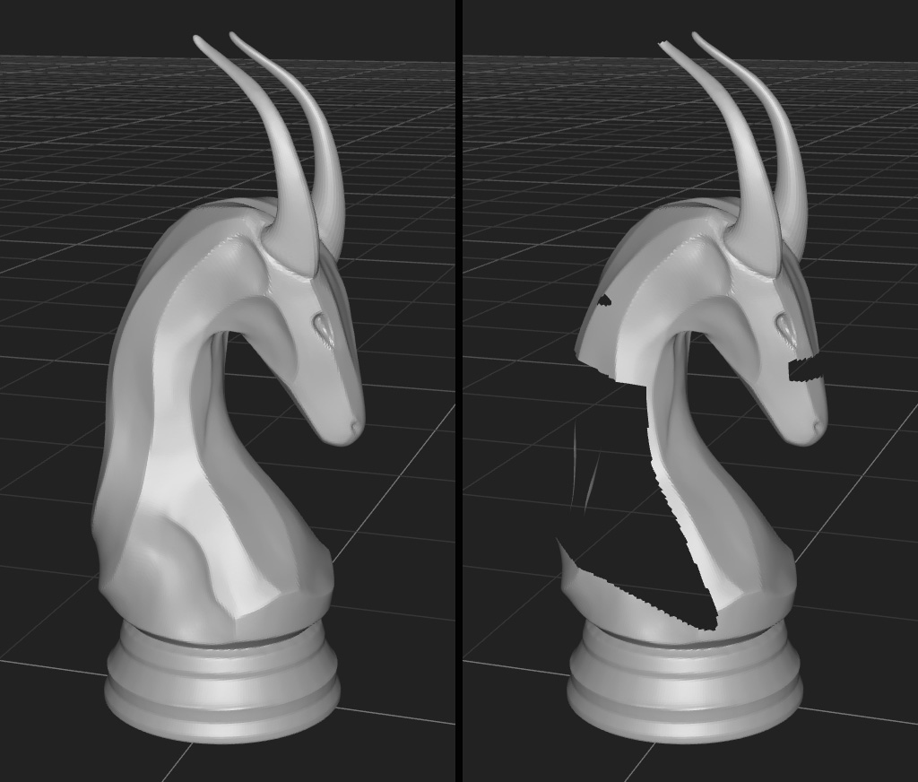
Now we get this:
5. Prettifying the patch
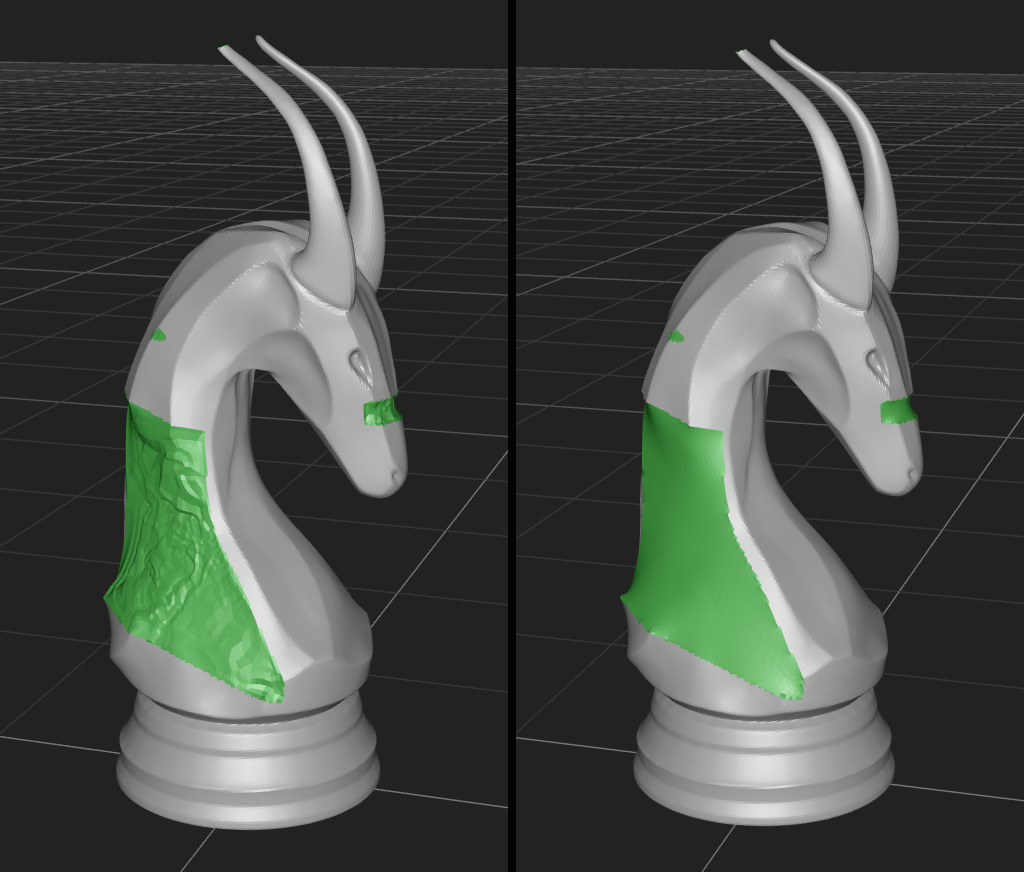
The results, as seen on the left of Fig. 2, are not pretty. Ideally, we’d come up with some scheme that either just smooths the entire patch, constraining it at the boundary, or one that intelligently adapts it to the surrounding geometry. The first method is presumably what ZBrush uses in its analogous algorithm:
It looks kinda like a piece of shrink wrap stretched between the border vertices. Maybe their way involves minimizing geodesic distances or something. The way I implemented something similar in meshy was simple: for every individual patch, take the vertices that aren’t on the border and set them to the average of their neighbors. Iterate until happy. One does have to take care around arrays of unique vertex references to ensure that, on any given iteration, one vertex’s new position doesn’t go into the calculation of another vertex’s new position.
Conclusion
The original paper gives a fix to the roughness problem that involves rebuilding the resulting patch by solving a Poisson equation, but I’ll likely never do that - the point of putting this thing into meshy was to give it some form of mesh repair until I put in a better (voxel-based) remeshing algorithm. Provided this algorithm doesn’t throw errors, it’s actually fairly robust - it should close any hole, provided it’s not too convex.